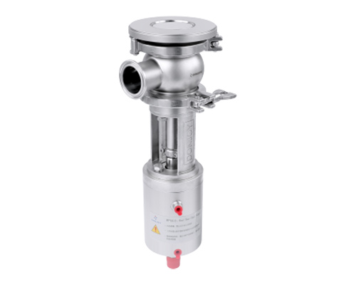
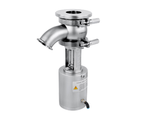
Donjoy Tank bottom valve
Tank bottom valve usually refers to a specially designed valve to control and regulate the bottom entrance or exit of storage, containers or other similar devices. There are two main designs of tank bottom valve -valve core contraction and valve core stretch.
Valve core contraction: This type of tank bottom valve usually uses a cone valve core to reduce or close the valve seat to control the flow of the fluid. When the valve core moves upward, it reduces the valve seat to prevent or reduce fluid flow. When the valve core moves down, it opens the valve seat and allows the fluid to pass. The main advantage of this design is that it can provide good sealing performance.
Valve core stretch type: This type of tank bottom valve usually uses a plate -type valve core, which can stretch or leave the valve seat at the opening to allow fluid flows. When the valve core moves up, it stretches the valve seat, which opens the valve and allows the fluid to pass. When the valve core moves down, it shrinks the valve seat to close the valve and prevent the fluid from flowing. The main advantage of this design is that it can provide a larger circulation area.
Technical Features
- Specifications: 1/2"-6", DN10-DN150
- Material: 316L/1.4404, ASME BPE 316L 1.4435 NB2 Fe≤0.5%
- Pressure: Vacuum to 10bar (1.0 Mpa)
- Temperature: -20℃ to +150℃, Depending on the seal material
- Seal: EPDM FKM HNBR PTFE
- Connection standard: DIN SMS ISO IDF RJT BS4825 ASME BPE 3A DIN11864 DIN11853
- Connection method: Thread, clamp, welding, flange
- Drive mode: manual, pneumatic, electric
- Finish: Ra≤0.6μm; EP=Ra≤0.3μm
- Certification: FDA 177.2600; 3A-53-06; Glass II USP Glass VI Chapter 88; GB4806.11; EG VO/1935-2004; PED/97/23/EC.
Tank bottom valve has a flexible valve combination and various functional configurations, such as:
Sterilization: This configuration usually includes a built -in sterilization device that can kill bacteria and other microorganisms in fluid flowing through valves.
Clamp insulation: This configuration usually includes a clip, which can maintain the temperature of the fluid to prevent it from cooling or heating when passing through a valve.
Linking buffer: This configuration usually includes a damping device that can buffer the impact of the fluid on the valve seat, thereby reducing noise and vibration.
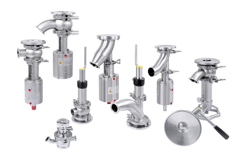
Different Connection Meathods
1, Welding 2, Clamp (recommended) 3, Aseptic flange 4, Nut 5, Thread 6, Vacuum clamp
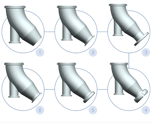
Connection method applicable to: spool shrink tank bottom valve
Different Connection Meathods
1,Welding 2, Clamp (recommended) 3, Nut 4, Thread 5,Aseptic flange
6, Vacuum clamp 7, Jacket insulation 8, 90°Elbow 90° 9, 45°Elbow 45°
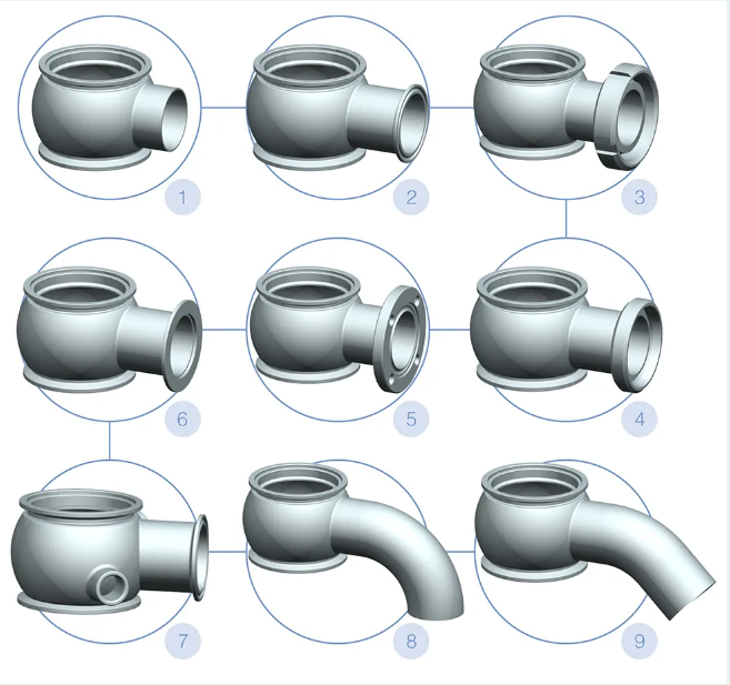
Connection method applicable to: spool shrink and spool extension tank bottom valve
Different Connection Meathods
1, Welding 2、Clamp (recommended) 3, Aseptic flange 4, 90°Elbow 90° 5, Nut type 6, Thread
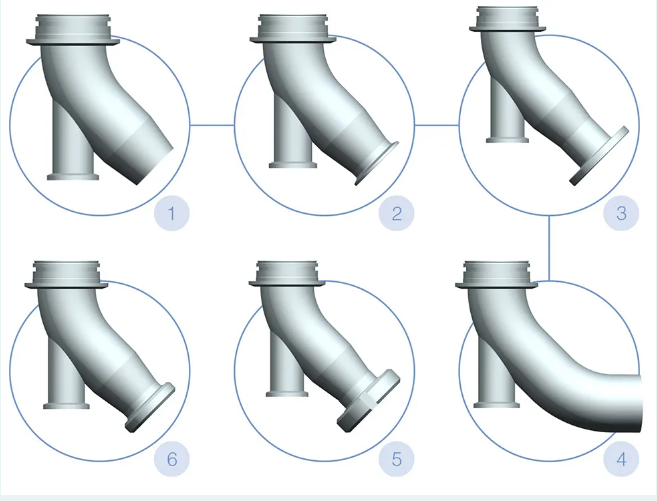
Applicable to: Spool extension type tank bottom valve.
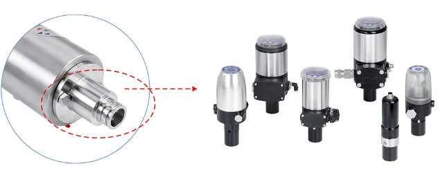
Various controllers for tank bottom valve
Feedback, Control unit, Valve positioner, Position sensor